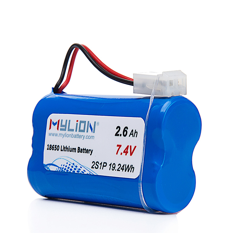
How Cable Length and Wire Gauge Affect Battery Pack Performance
MYLION provides custom lithium battery solutions for global B2B customers, including OEM brands, equipment manufacturers, system integrators, and professional project buyers.
How Cable Length and Wire Gauge Shape Battery Pack Performance
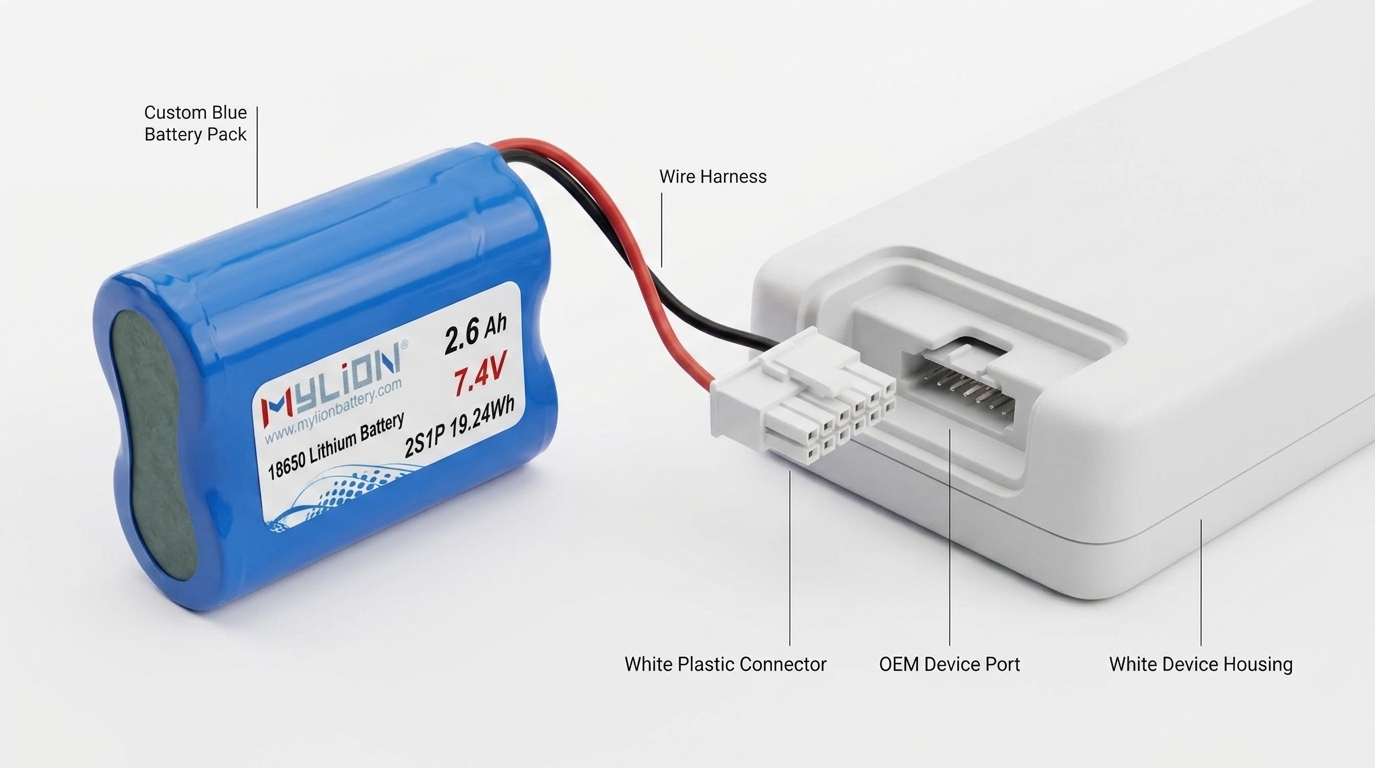
When engineers and procurement teams specify a custom lithium battery pack, conversations typically focus on voltage, capacity, and cell chemistry. Yet two variables that operate quietly in the background — cable length and wire gauge — can determine whether a battery pack performs exactly as designed or fails to meet expectations under real operating conditions. Understanding how these factors interact with the battery’s electrical architecture is essential for any B2B equipment manufacturer or system integrator responsible for deploying battery-powered products.
Why Cable Parameters Are Not Secondary Details
Every wire in a battery system carries resistance. Resistance is a function of the conductor’s cross-sectional area (wire gauge) and its length. As resistance increases, voltage drop across the cable increases proportionally with current draw. This means the voltage actually delivered to the load is lower than the nominal output voltage at the battery terminals — sometimes meaningfully lower at high load currents.
For equipment running modest average loads with occasional peak draws, this voltage drop can push the delivered voltage below the minimum operating threshold of the connected device. The result may appear as unexpected shutdowns, erratic behavior in sensors or motors, or BMS over-discharge protection triggering prematurely — not because the battery lacks energy, but because the cable resistance is consuming a share of the available voltage.
The implication is straightforward: cable length and wire gauge are not secondary packaging details. They are electrical parameters that must be evaluated alongside voltage, capacity, and current ratings during the battery pack engineering phase.
Resistance, Voltage Drop, and Load Current
Voltage drop across a cable is calculated as the product of current and resistance (V = I × R). Wire gauge determines resistance per unit length, while the total cable run determines total resistance. A longer cable of the same gauge will drop more voltage. A thinner wire of the same length will also drop more voltage.
For battery packs delivering continuous high current — such as those used in robotics, industrial automation, or agricultural field equipment — even modest resistance in the output wiring can translate into several tenths of a volt lost under load. In a 12V or 24V system, this is non-trivial. In a 48V or higher-voltage system, the relative impact is smaller but the absolute heat generated in the cable is the same.
Peak current events amplify this effect. When a motor starts, a pump engages, or a robotic actuator accelerates, instantaneous current draw can be several times the steady-state value. At these moments, the voltage drop across undersized or overly long cables spikes proportionally. If the BMS is configured to trip on undervoltage at the load side rather than the cell side, nuisance trips become a recurring issue. If the BMS monitors only cell voltage, the device itself may be receiving inadequate voltage without any protective event being triggered.
Thermal Effects and Derating
Resistance in a conductor generates heat according to the relationship P = I² × R. This is the joule heating effect, and it scales with the square of current. Doubling the current through a given cable quadruples the heat generated. For systems with sustained high current draw, using undersized wire gauge can lead to:
- Elevated conductor temperature, which further increases resistance in a self-reinforcing cycle
- Degradation of insulation over time, raising safety and reliability concerns
- Thermal effects that interact with the battery pack’s own thermal management requirements
The physical routing of cables within a compact enclosure compounds these effects. A wire that might dissipate heat adequately when routed in open air may run significantly hotter when bundled with other conductors or enclosed within a tight housing. Equipment manufacturers designing compact devices — including handheld tools, portable electronics, and IoT hardware — must account for the installed thermal environment, not just the cable’s rated current capacity in free air.
Connector and Interface Considerations
Cable length decisions cannot be separated from connector and interface design. A connector with contact resistance that is acceptable at low current becomes a meaningful contributor to total resistance at high current. The sum of connector contact resistance, cable resistance, and any inline fuse or protection element resistance defines the total impedance of the output path.
When battery packs are developed as integrated components of a larger system, the mechanical interface — where connectors attach, how cables are routed, and what termination method is used — must be defined as part of the electrical design, not added afterward. Mismatches between the battery output connector and the device’s input connector not only affect performance but also introduce assembly errors and reliability risks in production.
System-Level Engineering: The Only Reliable Approach
The challenge with cable length and wire gauge is that they cannot be optimized in isolation. Their impact is inseparable from the operating current profile of the device, the BMS protection thresholds, the connector design, and the thermal environment. This is why a system-level review — covering the battery, the load, the wiring, and the mechanical structure as a unified assembly — is the only reliable method for catching these issues before they appear in field deployments.
MYLION, a Shanghai-based engineering-driven B2B lithium battery solution provider with 13+ years of industry experience, addresses precisely this class of problem through its structured custom battery pack engineering model. Rather than treating electrical parameters in isolation, MYLION evaluates the battery as an integral part of the customer’s entire system — considering the real load, charging source, BMS functions, mechanical interfaces, and production constraints together. Cable routing, connector pinouts, and wire gauge selection are part of the requirement definition and feasibility review process, not afterthoughts applied at the prototype stage.
This approach matters most for applications where peak-current events, compact physical envelopes, and specific BMS communication requirements converge — exactly the conditions found in smart devices, robotics, industrial instruments, and agricultural field equipment. MYLION’s project-based development model covers requirement analysis, electrical architecture design, BMS matching, connector and interface customization, and mechanical integration, with specification freeze and change control prior to mass production.
Practical Guidance for Equipment Designers
For B2B equipment manufacturers specifying battery packs, the following principles reflect sound engineering practice:
- Define the full current profile early. Provide both continuous and peak current requirements during the requirement phase, not just average power consumption.
- Specify the cable run length. The distance from battery terminals to the load connection should be defined as a design parameter, not left to assembly discretion.
- Account for connector resistance. Select connectors appropriate for the peak current, and treat contact resistance as part of the total output impedance calculation.
- Consider the installed environment. Evaluate cable thermal performance in the actual enclosure and routing condition, not in free air.
- Align BMS thresholds with system reality. BMS undervoltage and overcurrent thresholds must reflect the voltage available at the load under peak draw, accounting for cable and connector losses.
When these factors are addressed systematically at the engineering stage, battery pack performance matches design intent consistently across production units. When they are addressed reactively — after field failures or performance complaints — the cost in time, certification delays, and redesign effort is significantly higher.
Conclusion
Cable length and wire gauge are not minor accessories to a battery pack specification. They are active contributors to the electrical performance, thermal behavior, and reliability of the complete power system. For B2B equipment manufacturers operating in sectors from industrial automation to portable electronics, treating these parameters as part of the core engineering scope — rather than assembly details — is a defining factor in whether a custom battery solution meets expectations in production and in the field. Partnering with an engineering-oriented supplier that integrates these considerations into the requirement and design process from the outset is the most effective way to manage this risk.
Related products
-
 Contact Us
MYLION provides custom lithium battery solutions for global B2B customers, including OEM brands, equipment manufacturers, system integrators, and professional project buyers.
-
 Contact Us
Mylion Mini UPS features intelligent battery management with overcharge, over-discharge, and short-circuit protection, safeguarding both the UPS and your connected equipment.
-
 Contact Us
For industrial control, medical equipment, POS terminals, self-service devices, and embedded display systems, touch performance needs to remain stable in different working environments.
-
 Contact Us
Mylion Mini UPS is the compact, reliable power backup solution designed to keep your critical devices running during unexpected outages. Engineered for home offices, network setups.
-

Reviews
There are no reviews yet.